Modulation: Where Radio Meets Data
Radio Waves carry information through space, so we can enjoy mobile phones, AM/FM car radio, satellite and cable TV, and WiFi laptop Internet services.
Some of the information we want to send starts off as digital data,
and some starts off as analog, but all can be carried over radio
frequency (RF) waves. Modulation is how they meet: information is
used to change the radio signal in some way, so it can be sent over the air or over wires, and later demodulated and heard, read, or seen.
Time and Frequency
Another way of look at radio waves is by frequency, instead of by time. (Frequency is just the number of complete waves per second.) So here the X axis is frequency and Y is the amplitude at that frequency.
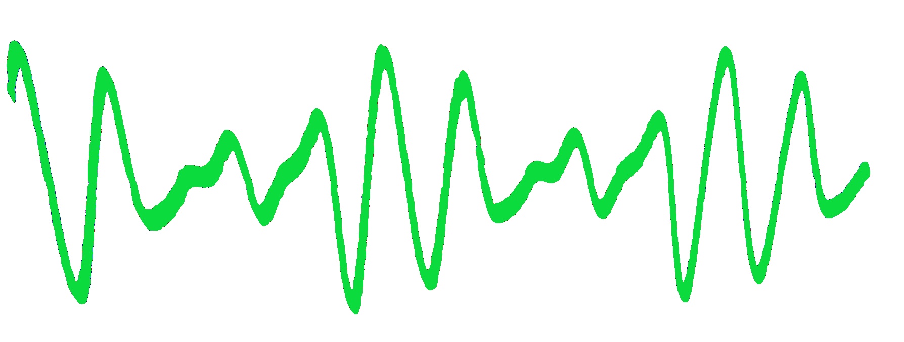
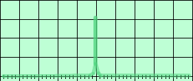
Here are time-domain and frequency-domain view of a 1 kHz audio tone. A time-domain view is what is normally seen on an oscilloscope:
A frequency domain view shows the tone as a single line, at the 1kHz frequency, and with a height corresponding to the original signal amplitude. A spectrum analyzer shows shis view:
AM Spectrum
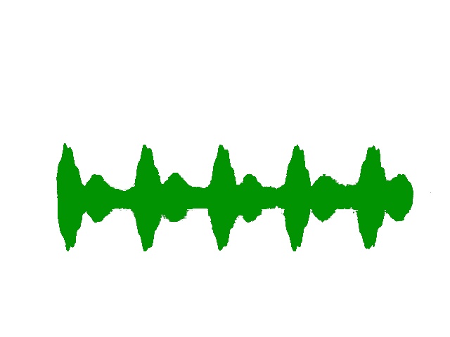
Here is a plot of an AM signal with an RF carrier of 1200 kHz amplitude modulated with a 1 kHz audio tone:
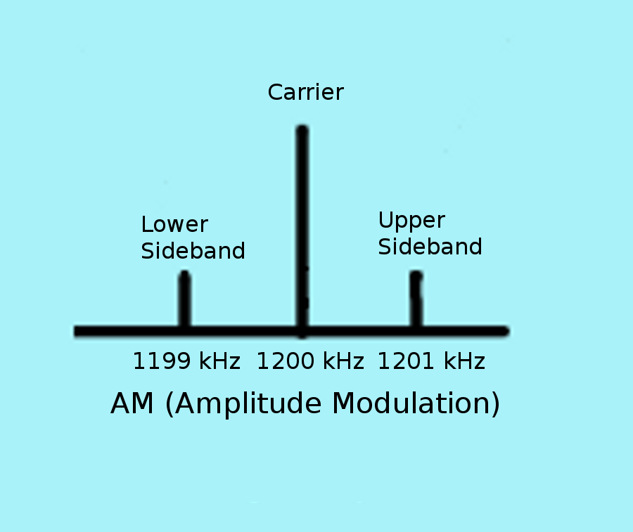
Notice the modulated radio signal has the carrier signal and two copies of the information (1 kHz signal), one above and one below. Multiplying the amplitudes of two signals gives the sum and difference of those two signals! The two signals are called sidebands, and they contain identical information, so one is redundant. So is the carrier, for that matter, since it never changes, and a signal that never changes carries no information!
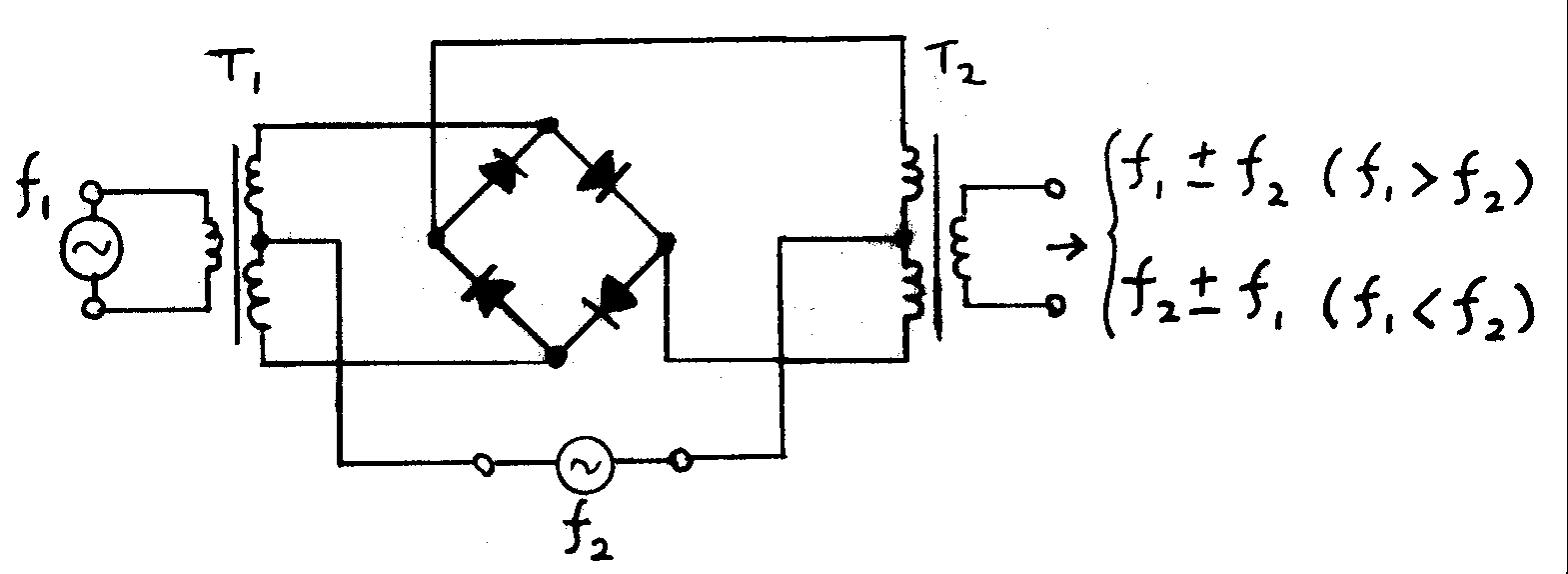
Modulation in Hardware
Mixing can be done with electrical components, or it can be done with software and a digtal to analog converter to produce an output voltage. All types of modulation modes can be produced in either way, though the more complex modulation modes require software at some stage.
Here is a schematic diagram of a mixer realized in electronics components:
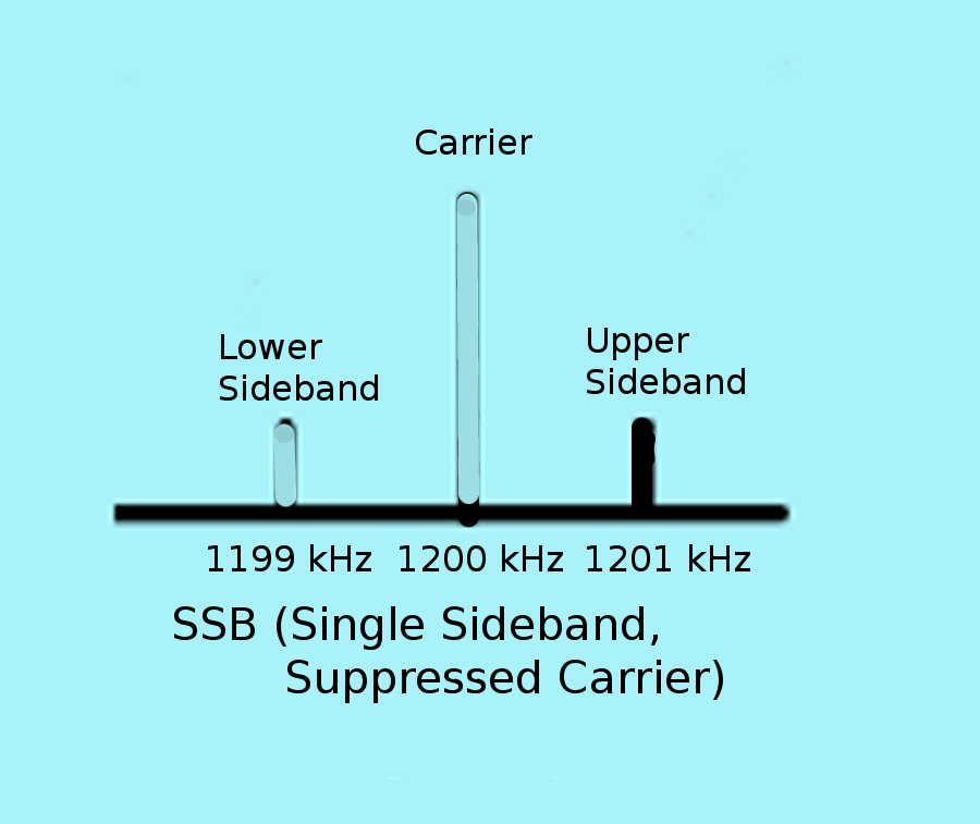
SSB: A More Efficient Mode for Audio
Single-sideband suppressed carrier (SSB for short) modulation eliminates the carrier and one of the two sidebands, and is more efficient though requires more coplex equipment. Note that there are two types, (+ and -, or upper sideband and lower sideband.)
SSB looks like this in a spectrum plot:
And in a time-domain plot:
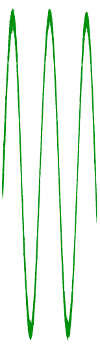
Note that the SSB transmitted output looks just like input, just shifted up to a much higher frequency!
AT&T Long Lines used SSB for long distance phone calls until the advent of digital telephony, and SSB remains strong in radio communications because of its efficiency and ability to be understood through noise.
FM for High Fidelity
Instead of modulating the amplitude, you can also modulate the frequency, or its close cousin, the phase. (Edwin Armstrong invented FM back in the early 1900's, but resistance from RCA and famous lawsuits from other engineers stunted FM radio until the 1950's.)
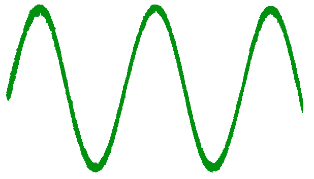
Compare the wave for AM and FM when modulated by a single frequency sine wave:
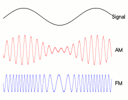
FM looks roughly like this for a 1 kHz tone and a 75 kHz "deviation":
A VHF FM radio broadcast station is allocated 175 kHz of bandwidth, whereas an MF AM station uses only 10 kHz.
An FM receiver "limits" the amplitude of the incoming signal and de-modulates the information from the change in frequency, so FM is much less sensitive to static and noise bursts than AM or SSB. FM generally requires more of the radio spectrum, or in other words, its "bandwidth" is higher, but in return it gives great audio fidelity.
Light Writing
The simplest digital encoding is a very simple amplitude modulation called Off-On Keying. The RF signal is simply turned off and on. (Note that a simple switch does this, and taking a cue from computers, we can think of it as multiplying by 1 or 0, making a switch a simple form of mixer.)
An early use of OOK was Hellschreiber, which sent text and pictures over telegraph wires (and later radio) by using off to mean white and on to mean black, and scanning quickly up and down, and more slowly left and right. (Early systems were entirely mechanical.)
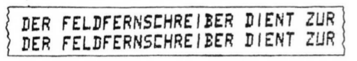 Feldfernschreiber Model 24a - 32, c. 1941
 Modern software implementation
The encoding used by Hellschreiber is a two-dimensional scan.
Off and On
Telegraphy is another form of off-on keying, and it uses two lengths of "on" to send two different symbols, with spaces between. A sequence of symbols represent a letter, and the encoding is chosen to make common letters shorter, and uncomming letters, numbers, and symbols longer. Here is an encoding still used today, in order of length:

Ward Cunningham
This encoding is International Morse code, though there are other less used ones. It is a digital OOK system which can be decoded by humans. In recent years, computer decoding systems have become available as well, though they still suffer in performance compared to humans, because of the lack of any clock or synchronization information.
Modulation for Digital Data
Similar techniques are used to modulate RF with digital data. One of the simplest means is to change between two frequencies, one for a binary 0 and another for a binary 1. This modulatation is called Frequency Shift Keying.
|
In the time domain, FSK looks like this:

FSK, time domain
|
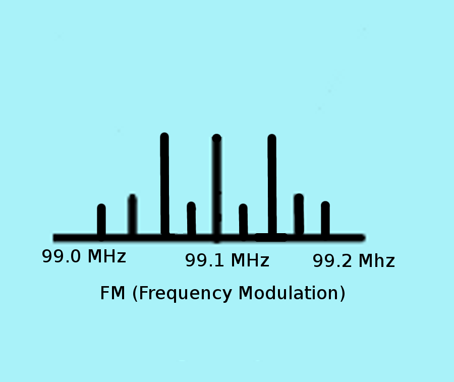
In a frequency domain view, an RTTY signal looks like this. Note the spreading of the spectrum due to the switching between the two frequencies.
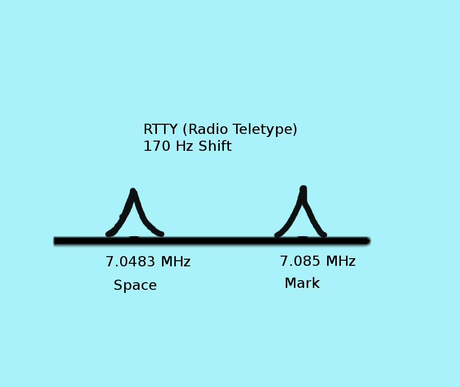
FSK, frequency domain
|
Digital modulation requires an "encoding" in addition to modulation. One of the first encodings was Baudot, which uses 5 bits to represent 31 symbols. One of the symbols is a "shift," which switches to a second set of symbols. In this way we can represent 26 letters, 10 numerals, and a host of punctuation marks and special symbols (such as backspace). Baudot was later extended to 7 bits of information and 1 bit of "parity" for error correction, in a format called ASCII. Most computers today use a descendent of ASCII.

Baudot punched tape
Modern Times, Modern Phases
Phase is close cousin to Frequency; if you change the phase of a radio wave, it makes the wave "skip" forward to another section of its waveshape.
The frequency domain plot looks very similar to that FSK plot, and the width is related to how quickly the phase changes. Because phase is a relative measure, it makes the design of self-clocking systems easy, and computer decoding becomes effective. Many digital modulation systems combine both phase and amplitude modulation.
Here is a Binary Phase-Shift Keying system, where a phase change is used to indicate a 0 and no phase change is used to indicate a 1, and amplitude is used both to send a clock signal and to reduce the amount of transmitted energy at the time when the sudden phase transition takes place, reducing bandwidth.
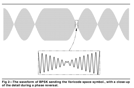
Peter Martinez
Like International Morse, it's advantageous again to use a variable length encoding, and since it's a computer-oriented mode, the encodign is specified as a conversion from the 8-bits of ASCII-like encoding to a variable length 2 to 11 bits, with 12-bit codes allocated uniformly for all codes 127-255.
More in the same space
Using four phase changes of 0, 90, 180, and 270 degrees coupled with amplitude changes gives advantages of more data in the same bandwidth, as long as the signal quality is good (thanks to Claude Shannon!). PSK signals are often visualized with a constellation diagram, showing the relative signal phases, and in more complex systems, amplitues as well. Here is a constellation chart showing 16-QAM which uses a combination of four amplitudes and phases to achieve 4 bits per transmitted symbol:
 Wikipedia
Encodings are again used to provide compression and error correction.
Internet cable modems using the DOCSIS-3 standard use 64-QAM and 256-QAM modulation on radio frequencies in the UHF range and carried over coax cables into your house.
Modulation in Software
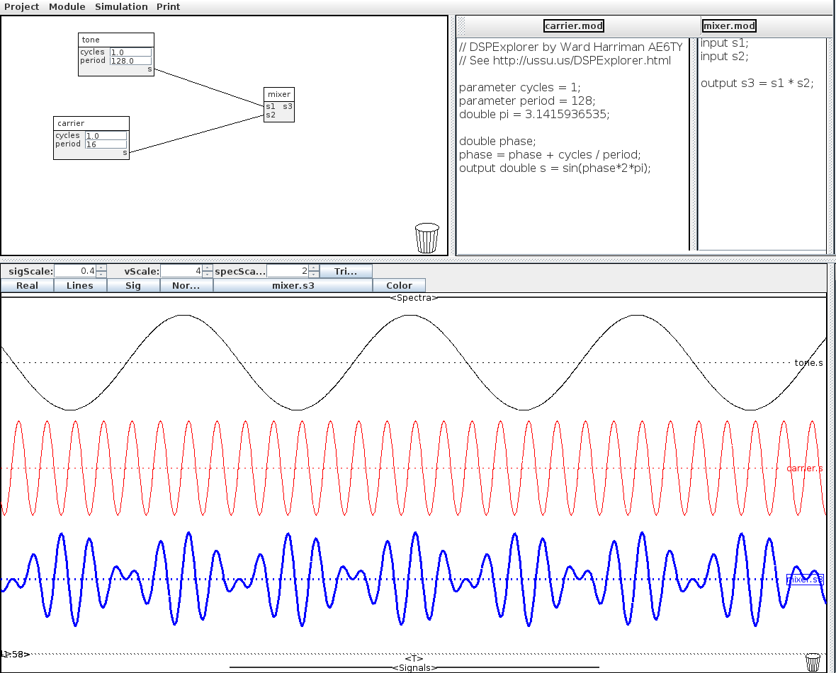 DSPExplorer by Ward Harriman, AE6TY
Credits
Girl with microphone clip art licensed from the Clip Art Gallery on http://DiscoverySchool.com
Antenna public domain image from http://www.clker.com/clipart-2775.html">http://www.clker.com/clipart-2775.html.
Peter Martinez PSK31 image from http://www.arrl.org/files/file/Technology/tis/info/pdf/x9907003.pdf
Mixer image from http://en.wikipedia.org/wiki/Frequency_mixer
Feldfernschreiber image from http://www.nonstopsystems.com/radio/Feldfernschreiber-manual-translated-V1-2.pdf
Morse Code Forever image by Ward Cunningham, http://c2.com/~ward/morse/
16QAM image from Splash, http://commons.wikimedia.org/wiki/File:16QAM_Gray_Coded.svg
Diode ring mixer image from Shimaden, http://ja.wikipedia.org/wiki/利用者:しまでん
FSK time domain image from Ktims, http://upload.wikimedia.org/wikipedia/commons/3/39/Fsk.svg
AM/FM wave image from Berserkerus, http://en.wikipedia.org/wiki/File:Amfm3-en-de.gif
Baudot tape from Tim Watson (KB1HNZ), http://www.qsl.net/ws1sm/digital.html
DSPExplorer software by Ed Harriman (AE6TY)
References
http://www.arrl.org/digital-data-modes
http://www.radio-electronics.com/info/rf-technology-design/pm-phase-modulation/what-is-psk-phase-shift-keying-tutorial.php
http://en.wikipedia.org/wiki/Frequency_mixer
http://en.wikipedia.org/wiki/DOCSIS
http://www.w1hkj.com/FldigiHelp-3.20/Modes
http://ae6ty.com/DSPExplorer.html
Leigh L. Klotz, Jr. WA5ZNU