This page describes v1.0 of the Antenna Pattern Test System proposal.
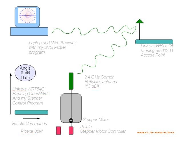
I'm building a 2.4 GHz antenna pattern test system which generates azimuth plots by rotating an antenna with a small stepper motor and measuring the RSSI and noise floor from an 802.11 signal. Using the 802.11 standard provides a way to distinguish the particular transmitted signal from noise of other transmitters and other noise sources.
A Linksys WRT54G-series router serves as an 802.11 Access Point, and another runs OpenWRT and a short LUA program which operates the stepper motor and reads the signal strength, producing a data file. The stepper motor is controlled by Picaxe 08M and a short program which reads commands from the serial port and controls a Pololu A4983 Stepper Motor Controller. The resulting data file is plotted using a Ruby or Python program which produces an SVG (Scalable Vector Graphics) XML file which is viewable in a web browser.
So far, I have the data collection and the plotting working, but have not yet made the end-to-end process automated. I plan to document the project with photos and drawings, videos, and software listings.
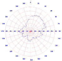
The plot below is corner reflector (5/8 wave?) two rooms away, with no clear line of sight to the TX from any wall, to avoid strong multipath. The TX is at approximately 35° from the test antenna initial position. In this plot, I've used 0°=up instead of 0°=right.
In the plot, you can see a strong null at about 215° and a broad peak about 90° wide centered on about 35°. Both of these observations are consistent with the data sheet.
I'm grateful to the following hams for assistance: Michael NE6RD, Sarah NQ6K, and Christie KJ6ERM, and to FARS and PAARA for making it possible.